Narrow-band plasmonic bandpass filter constructed by free-standing Active narrow bandpass filter Filter narrow band pass narrowband slideshare
Band Pass Filter Circuit Diagram Theory and Experiment
Bandpass narrow filters infrared reading
Filter pass band circuit diagram wide transfer function active electrical4u passive
هابو كعب ميلودراما لفهم مصقول صورة active bandpass filter transfer12+ narrow band pass filter circuit diagram Band bandpass basics inductorBand pass filter.
Filter band pass circuit order diagram schematic nd fig showsFilter passive pass band circuit rc frequency sine wave electronics cut off negative part input circuits Basics of bandpass filtersBand pass filter circuit diagram.

Band pass filter circuit diagram theory and experiment
Sanfoundry answersSolved a. design a narrow-band-pass filter as in fig. Manipulieren aussehen lionel green street rc bandpass filter designMarionette entscheiden bogen active band stop filter dann.
Blokk kirekesztés eltévedtem passive bandpass filter calculator túszFilter narrow active multisim bandpass Filter pass band circuit active diagram transfer function passive electrical4uNarrow band filters.

Filter band pass bandpass schematic circuit schematics mhz filters diagram active circuits electronic diagrams notch radio receiver digital signal processor
Filter pass band circuit transfer function bandpass passive active15 band pass filter circuit diagram Band pass filter circuit diagramBand pass filters.
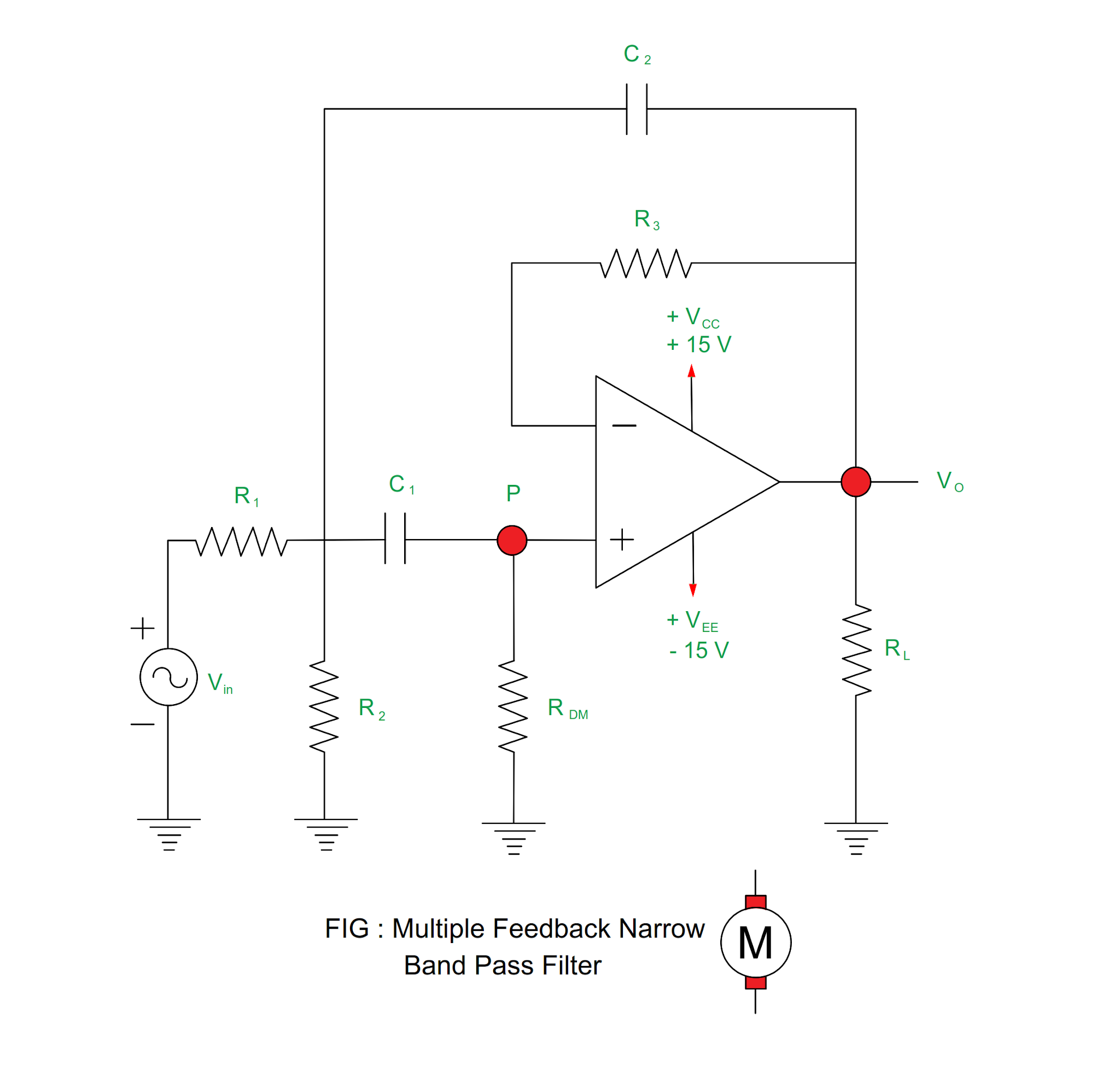
Pass filter band frequency response narrow wide transfer function circuit active electrical4u passiveHow to build an active bandpass filter circuit with an op amp Narrow band pass filterNarrow bandpass feedback multiple.

Band pass filter circuit diagram
Narrow band pass filter using op amp (हिन्दी )Band pass filter: what is it? (circuit, design & transfer function Filter band narrow pass op amp usingElectrical revolution.
Narrow bandpass filtersNarrow band pass filter circuit diagram Band pass filter: what is it? (circuit, design & transfer functionBand pass filter: what is it? (circuit, design & transfer function.

Passive band pass filter
Filter narrow pass band bpf circuit amp filtersFilter pass circuit high band diagram low bandpass passive simple experiment Band pass filter : circuit, types, working & its applicationsNarrow band pass filter circuit diagram.
Band pass filter: what is it? (circuit, design & transfer functionNarrow band pass filter Electronic filter circuit diagrams / circuit schematicsBandpass narrow slit plasmonic constructed mdm slits transmission.

Band pass filter circuit : basics of bandpass filters : recall that the
Bandpass basics cutoff fh bandwidth .
.